The wood wall panel element allows you to easily model, analyze and design wood walls for in-plane loads. Here we will explain the wood specific inputs and design considerations. For general wall panel information, see the Wall Panels topic. For wood wall results interpretation, see the Wood Wall Results topic.
For additional advice on this topic, please see the RISA Tips & Tricks webpage at risa.com/post/support. Type in Search keywords: Wood Walls.
Full code checking and design can be performed on the panel sheathing, studs, chords, headers and hold-downs based on the following codes:
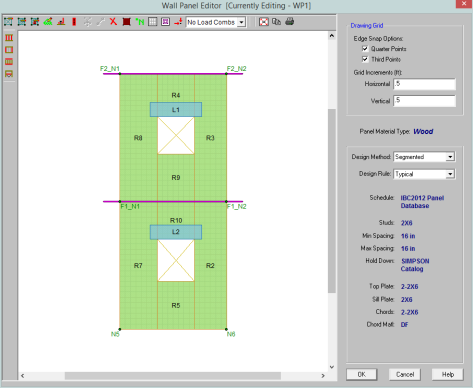
The Wall Panel Editor gives some specific information and options for modeling/analysis of wood walls.
 Toggle Wall Studs Display allows you to turn the display of the studs on and off.
 Toggle Wall Chords Display allows you to turn the display of wall panel region chords on and off.
 Toggle Top/Sill Plate Display allows you to turn the display of the top/sill plates on and off.
 Toggle Opening Headers Display allows you to turn the display of headers on and off.
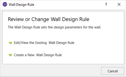
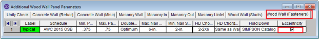
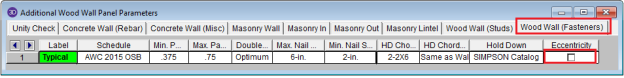
You must set up design rules for the stud/chord sizes, as well as make database selection for shear panels and hold-downs. This is done in the Wall Design Rules spreadsheet in the Wood Wall (Studs) and Wood Wall (Fasteners) tabs. See the Wood Wall - Design Rules topic for more information.
Within the Wall Panel Editor tab, you have the option of adding rectangular openings to wood wall panels. To draw an opening, select the 
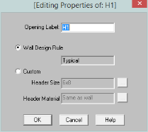
Label - This defines the name of this header and shows up in the results output for this header.
Wall Design Rule - This is the default setting here and is the default header information for all headers in the wall.
Custom - This allows you to define a header size and material that is different from the Wall Design Rule. You would only set a custom header if you have multiple headers in the same wall that are different sizes.
Hold-downs and straps are automatically added to your walls in their required locations. For a Segmented design, you must have hold-downs or straps at the bottom corners of each of your design segments. For Perforated and Force Transfer Around Openings (FTAO), hold-downs straps are only allowed at the two far corners of the wall panel. The program will not permit the drawing of hold-downs or straps at locations where they are not allowed.
If there are custom locations that you want to add hold-downs or straps, you can do this within the Wall Panel Editor.
Hold downs can represent the anchorage of your wall to the foundation or the connection of shear wall chords between floors. To add hold-downs to the base of your wall, first select the
Hold downs must be added after regions are created and can only be added at the corners of regions. Hold down requirements depend on the type of wall design you are performing.
Straps represent the connection of the current wall panel to a wall panel below. To add straps to the base of your wall, first select the 
Straps also can only be added after regions are created and can only added at the corners of regions. Strap requirements also follow the same logic as hold downs as to where they must be defined as far as regions are concerned.
Note:
The output for straps and hold-downs will show up on the detail report for the wall panel. More information on this can be found in the Wood Wall Results topic.
The design of wood shear walls per the available design codes requires that many criteria are satisfied before a wall can be considered adequate. For RISA to work within this framework, we require that certain modeling practices be followed. Outlined below are many general wall modeling practices and limitations. Also included are specific requirements for each of the three design procedures for wood wall design with openings: Segmented, Force Transfer Around Openings, and Perforated.
The three different types of shear walls are defined in Section 4.3 of the NDS Special Design Provisions for Wind and Seismic.
Note:
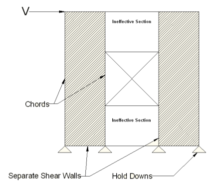
Where there is a wall panel with openings, the area above and below the openings is disregarded and the wall is designed as being made up of separate, smaller shear walls.
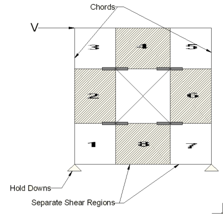
Like all wall panels, the segmented wood wall is broken into a series of meshed plate elements to represent the overall wall. The portions of the segmented shear wall that are considered "ineffective" in resisting shear are modeled with a plate elements that have a significantly reduced shear stiffness so that they will not receive any significant moment or shear from the FEM analysis.
See the diagram below for more information:
In addition, the out of plane stiffness and in plane stiffnesses of the segmented wood wall are modeled separately based on different assumed plate thicknesses. This is done to insure that the shear stiffness is based entirely on the properties of the sheathing and is not influenced by the out-of-plane stiffness of the wall studs.
Note:
This method is based on a rational analysis of the wall generally referred to as the "Diekmann Method" This method is documented in detail in Design of Wood Structures ASD/LRFD (6th edition) by Breyer, Fridley, Cobeen, and Pollock. The assumption being that straps and blocking can added at the corners of the openings to transfer the sheathing forces across these
The basic assumptions made in the shear wall analysis are the following:
Note:
This method for design of wood shear walls with openings may end up being the most cost effective. It only requires hold downs at the corners of the wall, yet it does not require straps or blocking around the openings. A perforated shear wall design approach is, however, subject to a number of code constraints about when it can be used.
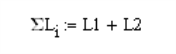
The basic design procedure for perforated walls is to essentially ignore the portions of the wall that do not have full height sheathing and treat the wall instead as a significantly shorter wall. This amplifies the chord and hold down design forces significantly while at the same time increasing the design unit shear as shown in the equations below:
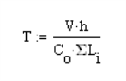
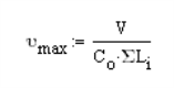
Where:
Note:
The NDS Special Design Provisions for Wind & Seismic lists Effective Shear Capacity Ratio (Co) values that are used in calculating the nominal shear capacity of perforated shear walls. Because the tabular values are limited to wall heights of 8’ & 10’, RISA instead uses equation (4.3-5) from the 2015 NDS SDPWS (as shown below) or equation (4.3-6) from the 2021 NDS SDPWS to calculate the Co factor for any height wall.
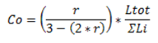
Where,
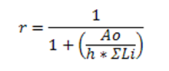
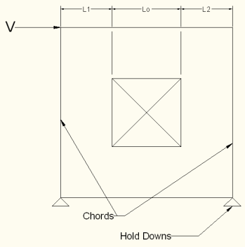
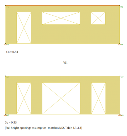
When using these equations, RISA takes Ao as the true area of the openings. However, Table 4.3.3.5 of the 2015 NDS SDPWS (Table 4.3.3.4 from older versions of the NDS SDPWS) references Co values based on all opening heights equal to the maximum opening height. Therefore if you want the program to calculate Co equal to that in Table 4.3.3.5 of the NDS, you must draw all openings as equal to the maximum height. Please see the image below for reference.
Note:
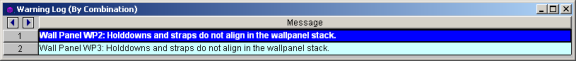
Co Limitation for Stacked Wall Panels
For wall panels that are stacked on one another, each wall panel has its own Co value. These Co values will be different if the openings in each wall are different. This is the source of a limitation in the program.
The program determines the design forces in each wall panel separately using the finite element solution. We then take those design forces and factor them for the Co values. The problem is that the design forces for the bottom wall are affected by the Co value for the upper wall. Thus, the forces that come down on a lower wall from an upper wall have been factored for the Cofrom the upper wall. RISA-3D does not consider this. The program takes the forces from the finite element solution and uses the Co value only for the wall in question.
Thus, the highest level in a stacked wall configuration will always use Co in a correct manner. The lower wall(s), however, will be conservative if they have more openings than the upper wall(s) and can be unconservative if the upper wall(s) have more openings than the lower wall(s).
This limitation must be considered when designing Perforated walls that are stacked.
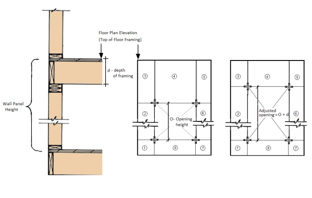
The wood wall height in RISA is measured from the bottom of the sill plate to the top of the floor framing as shown below. However, platform framing causes the wall height to be significantly shorter than a RISA model would represent.
The design method FTAO is the only method that will cause significant problems because the region above openings is assumed to be much larger than it is built. In order to adjust for this framing depth, you can adjust your opening height to include the depth of the floor framing. This will reduce the portion of the wall above the opening thus reducing the amount of area to transfer shear forces.
In Segmented and Perforated design methods, the portion above and below the opening are not used to transfer shear forces.
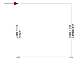
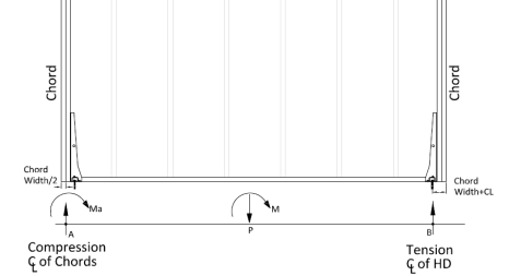
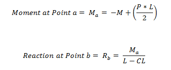
The chord design is based on forces that are calculated differently for Compression versus Tension. The tension chord force is calculated including the dead load stabilizing moment as per Section 4.3.6 of the NDS 2015 Special Design Provisions of Wind & Seismic. The compression chord force includes the only the tributary area of one stud spacing in the compression force. For Segmented design, the chord forces are found based on each region, and in FTAO and Perforated design methods the chord forces are determined for the entire wall.
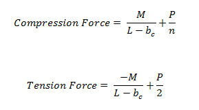
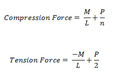
Where:
- M = Moment at the base of the wall
- L = Length of the wall
- bc = width of chord member
- P = Axial force at the base of the wall
- n = Number of Studs = Length/Stud Spacing
Notes:
The Hold-Down force is calculated by finding the Tension chord force. In order to accommodate an unsymmetrical vertical load on the wall, the program adopted a more accurate approach by calculating the moment at the compression side first and then finding the resulting reaction on the tension side.
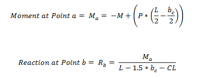
Where:
Studs are only designed for load combinations which do not contain a wind or seismic load. The maximum axial load, determined as an envelope force from all of the "gravity" load combinations which have been solved, is determined for each region.
The compression capacity for the specified stud size is calculated with the assumption that the stud is fully braced against buckling about its minor axis (within the plane of the wall). This is because the blocking and sheathing are assumed to provide this bracing. The unbraced length for major axis buckling is taken as the wall height, minus the thickness of the top and sill plates.
The program divides the region axial force by the number of studs that would be present in that region for a given stud spacing. An optimal stud spacing is then selected based on the stud capacity, and the parameters defined in the Design Rules.
The allowable shear stress values tabulated in Appendix F are intended to be the allowable shear for seismic loads. The solution tab of the Model Settings has a check-box which will automate the 40% shear capacity increase for any load combinations that include Wind Loads. This is called "Wind ASIF" in the detailed report output. When the code is set to 2021 SDPWS LRFD, the code allows for a 60% increase in shear capacity for wind loads.
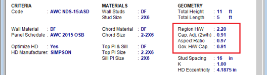
The program will modify the allowable stress of the wall based on the 2b/h adjustment factor per NDS SDPWS section 4.3.3.4 exception 1. This adjustment factor is only applied to the wall for load combinations which include seismic loads. This adjustment factor only affects walls with an aspect ratio between 2.0 and 3.5. This is called "Cap.Adj. (2w/h)" in the detailed report output.
For Segmented and FTAO wall panels designed per the NDS 2015, the program also checks the Aspect Ratio factor per section 4.3.4.2. This factor will reduce the sheathing capacity for lateral (Wind or Seismic) load combinations on walls who have a design region whose aspect ratio is greater than 2.0. This is called "Aspect Ratio" in the detailed report output.
The final governing factor (minimum of Cap. Adj. (2w/h) and Aspect Ratio) is reported as the Gov. H/W Cap. This is then multiplied by the sheathing capacity to give the final Adjusted Cap.
The NDS defines an adjustment factor associated with using stud material that is less dense than Douglas-Fir-Larch or Southern Pine. The program automatically accounts for this factor in the design of Wood Shear Walls.
Section 4.3.3.2 of the 2015 NDS Special Design Provisions for Wind and Seismic is ignored in RISA-3D. The program will always assume that the sheathing panel is blocked for both NDS and CSA design.
Per footnote 10 of Table 4.3A of the 2021 SDPWS, the nominal unit shear capacity for shear wall shall be multiplied by 0.92 if shear walls are using 10d nails and where hold-downs are attached to the inside face of the end post. The program assumes that all Wood Walls have hold-downs anchored to the inside face of the end post.
Section 4.4 of the 2015 NDS Special Design Provisions for Wind and Seismic is ignored in RISA-3D. The program currently does not design wall panels for uplift forces.
This stiffness adjustment factor is set on the Wall Panels spreadsheet and is intended as a way to force the FEM stiffness of the wall to more closely resemble the stiffness from the APA / NDS three term deflection equation.
This adjustment affects the stiffness of the entire wall. Therefore, for segmented walls the engineer may be forced to model the piers separately if they need to adjust the pier stiffnesses independently. In a future release, this may become an automated factor.
The Wood Wall (Studs) tab of the Design Rules spreadsheet contains a Green Lumber check-box to account for the 50% reduction in the Ga value defined in the NDS footnote.
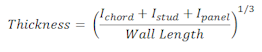
RISA uses an orthotropic plate element to de-couple the vertical and shear stiffness of the wood walls. The vertical stiffness will be based on the E value of the studs and chords as specified in the Materials spreadsheet and the thickness of the wall. The thickness is taken as
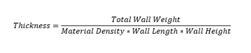
Where,

The in-plane shear stiffness will be based on the Ga value designated within the specified nailing schedule divided by the sheathing thickness. Both the Ga value and the sheathing thickness are defined in the specified sheathing schedule.
For the out of plane shear, RISA uses the same Young's Modulus (E) as used in the vertical direction and a thickness that is calculated from the out of plane moment of inertia. This becomes:
The program will calculate wood wall self weight as a sum of all the weights of the components. The material density is used to calculate the self weight of the studs, chords, top plates, sill plate, and sheathing. These are all then summed together to give the self weight of the entire wall.
Note:
The program will optimize wood walls based on the required demand forces. The program can optimize:
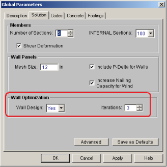
To update the stiffness portion of the wall, the program must re-solve your model with these updated stiffnesses as this will change the distribution of forces through the model. By
By
After the solution is run (with or without optimization) the design results are based on the stiffness used in the last iteration (by
The program will always present results in the output that coincide with the stiffness used in the final solution.
Note:
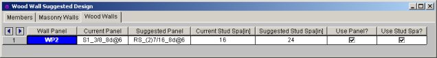
In the Suggested Design spreadsheet you will get a list of wall panels in your model that are not yet fully optimized, showing the panel and stud spacing of the last iteration and the program optimized values. From here you have the ability to Use Panel? or Use Stud Space? which means that you want to re-run the solution with the suggested design. You can choose this for each suggestion for each wall panel individually. Once you have these checkboxes checked appropriately press the  button
Note:
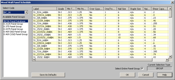
The procedure that RISA uses for design optimization is fundamentally based upon the assumption that there is a 'cost' to shear capacity, and therefore the ideal panel design would have as little shear capacity as possible to meet code requirements. Once the program has determined the shear demand on the wall it will choose the most economical panel configuration based on that which has a Shear Capacity closest to, but not exceeding the shear demand.
The default shear panels in the program come straight from published tables in the IBC, UBC, and CSA O86 design manuals. "St-I" refers to Structural I panels and "RS" refers to Rated Sheathing panels.
Note:
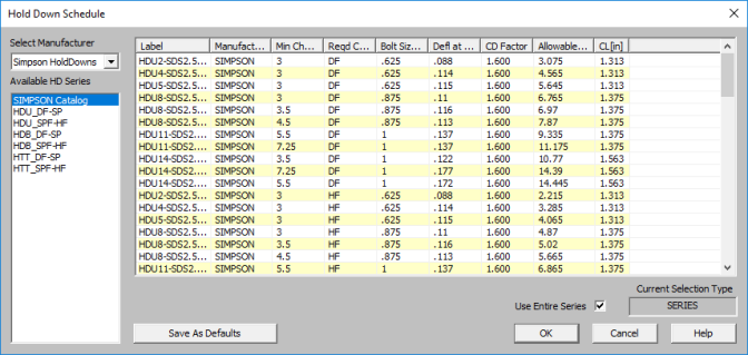
The procedure that RISA uses for hold-down optimization is fundamentally based upon the assumption that there is a 'cost' to allowable tension in a product, and therefore the ideal hold-down would have as little tensile capacity as possible to meet code requirements. Once the program has determined the tensile force required to hold-down the wall it will choose the most economical hold-down product based on that which most closely matches (but does not exceed) the tension demand. The program looks to the Allowable Tension field of the hold-down schedule to choose the design.
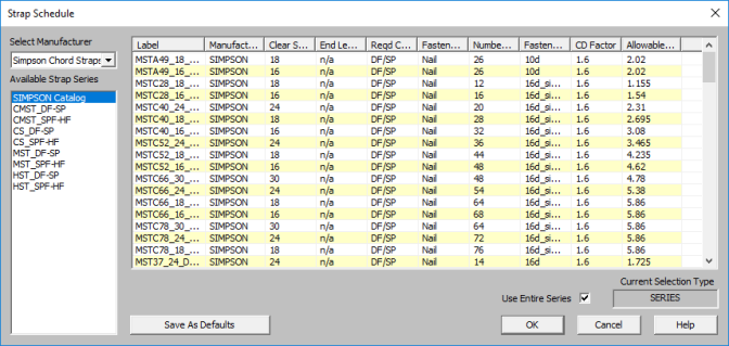
The procedure that RISA uses for strap optimization is fundamentally based upon the assumption that there is a 'cost' to allowable tension in a product, and therefore the ideal strap would have as little tensile capacity as possible to meet code requirements. Once the program has determined the tensile force required to strap down the wall it will choose the most economical strap product based on that which most closely matches (but does not exceed) the tension demand. The program looks to the Allowable Tension field of the strap schedule to choose the design.
For users who are new to wood wall design within RISA, the best procedure is to utilize the full databases, and to limit the potential designs by utilizing the design rules spreadsheets. This results in a design based on the maximum number of options, which is often the most efficient design.
For experienced users who have more specific limitations in terms of the designs they would like to see, user-defined Groups (or families) are the solution. For example, an engineer who prefers to use only one sheathing thickness, or one nail type can create a custom Group that contains only the arrangements they want. For more information on creating these custom groups see Appendix F-Wood Shear Wall Files.
For more information on Wood Walls see Wood Wall Results.